Slope Stability Radar Alarm Threshold Validation at Telfer Gold Mine


 GroundProbe’s Global Practice Lead – Geotechnical Advisory, Albert Cabrejo, and Head of Geotechnical, Peter Saunders
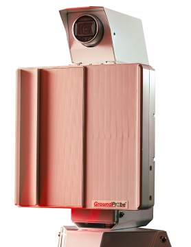
GroundProbe’s Slope Stability Radar (SSR) is the primary monitoring tool at the Telfer gold-copper mine, located in the Great Sandy Desert of Western Australia. The SSR manages slope instability risk to personnel and equipment in the steep, brittle, rock environment of the Telfer Mine.
Economic and Safety Impact
Exclusion from high-value mining areas due to a risk to personnel or equipment is part of safe mining operation. Most operations are satisfied if alarms trigger a few days prior to collapse, however, early exclusion from valuable ore reserves and long production delays can be costly. Strong risk management controls can be applied based on assumptions that an observed deformation rate is significant, however, in many cases the risks have not been rigorously evaluated.
Analysis to develop an improved understanding and effectively manage the risk of continuing to operate in an area apparently at risk of collapse can be an extremely valuable exercise for a mining operation.
Effective real-time application of collapse forecasting techniques using velocity analysis software tools, such as the MonitorIQ, can minimise the risks associated with wall collapse and minimise disruption to mining operations. Inadequate training and documentation relating to alarm threshold justification is a significant potential business risk, as these are often considered the front-line-of-defense in high-risk, high-exposure mining areas.
Trigger Action Response Plans (TARP)
GroundProbe’s MonitorIQ software allows application of six types of alarms, which can be applied as stackable alarms and trigger in sequence leading up to collapse. Hierarchical alarms are also set for each different alarm type with different thresholds intended to trigger in sequence. These alarms can be aligned with a site’s geotechnical Trigger Action Response Plan (TARP) – a policy of planned responses to trigger events. Figure 1 shows diagrammatically how the MonitorIQ alarms can be aligned with a site TARP.

Alarm Application Methodology
Deformation and velocity alarms are generally the most frequently applied and easily understood alarm types for slope monitoring. Once an increased level of risk is identified, the other stackable alarms can be applied. A broad range of alarm strategy seems to be applied within the industry, where no deformation trends have been observed prior to setting alarm thresholds. As a result, alarm thresholds are often arbitrary, or based loosely on specific site experience. Additionally, testing of radar alarm thresholds is also not common industry practice .
When applying a targeted alarm strategy, areas showing signs of deformation are isolated and set with alarm parameters to prevent unwanted alarms being triggered from non-hazardous material. When a linear deformation trend is identified, the velocity is noted, and a new velocity alarm can be set to alert the user of the onset of accelerating slope movement. As accelerating slope movement is observed, the associated risk increases and so does the assigned TARP Trigger level.
At this stage, forecasting methods can be applied and inverse velocity alarms can be set. As the onset of failure occurs and new fractures begin to form, final stage alarms, coherence and tracking, can be set to alert the engineer that the surface of the slope is beginning to deform or fracture significantly between scans or the velocity is approaching the limits of the radar’s ability to track the deformation effectively (>7.85 mm/scan).
Telfer Analysis
Analysis was undertaken of the appropriateness of alarm thresholds and accuracy of collapse forecasting at the Telfer Mine, using different time windows of 60, 180, 720 and 1,440 minutes. Table 1 lists the collapses that were analysed for alarm threshold validation.

Forecasting Collapse time
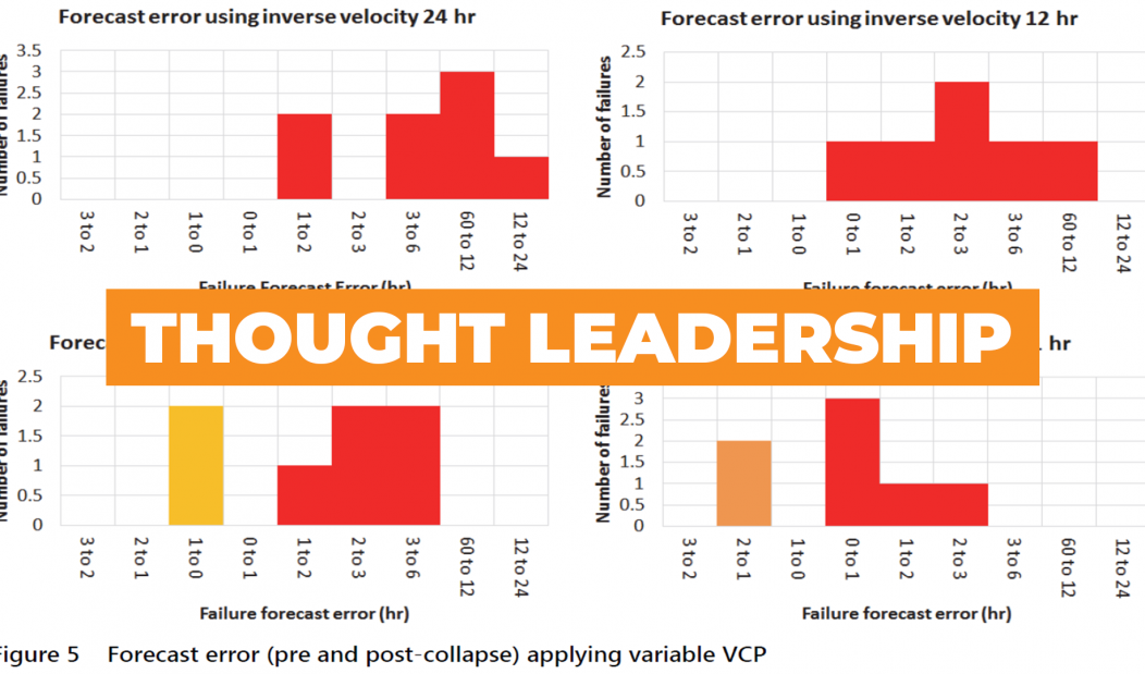
Prior to each collapse, a forecast was made, allowing an adequate time to evacuate personnel and machinery from the area of concern. The error between the actual failure time and the forecasted failure time was measured for each collapse. The histograms in Figure 5 display the forecast error for different time windows. The orange bars correspond to events where the failure prediction was one to two hours before or after the actual failure event. The red bars correspond to cases where the failure prediction was greater than two hours after the actual failure time.

Figure 4 displays the inverse velocity values measured at, or very close to, the time of collapse applying different time windows.

The accuracy of the inverse velocity method to forecast failures at Telfer was investigated by applying various time windows. Application of a 60-minute time window resulted in a collapse forecast between two hours prior and three hours post-failure. A 180-minute time window resulted in a collapse forecast between one hour prior and four hours post-failure. A 720–1,440-minute time window resulted in a collapse forecast time up to 14 hours post-failure.
Time Windows
Comparing velocity over various time windows was found to be a useful analysis technique. The data shows that applying shorter time windows resulted in a more accurate collapse forecast. However, the larger time window was useful for early detection of significant changes in deformation trends, allowing the detection of collapse trends as early as 36 hours prior to failure. A balance should be found between using short time windows with less usable ‘noisy’ data and longer time windows with smooth data and clear trends.
Velocity Alarm Thresholds
Collapses at Telfer can generally be described as rapid, brittle failures where relatively high-velocity thresholds will not generally provide an adequate notification period prior to collapse. Applying a velocity alarm threshold of 1 mm/hr with a short 60-minute time window resulted in frequent unwanted alarms due to data ‘noise’. A threshold of 2 mm/hr resulted in an insufficient notification period when tested on previous collapses. A 1.5 mm/hr velocity was found to be appropriate in all cases tested. It is likely that this value could be further refined with repeated ongoing back analysis.
Deformation Alarm Thresholds
Deformation alarms were rarely applied on site at Telfer at the time however, the results suggest that their application may provide an additional layer of control when applied in conjunction with velocity and other stackable alarms. A 1 mm/hr velocity alarm had been applied on-site previously with limited success due to frequent unwanted alarms caused by noise in the data. A 4 mm/4 hr deformation threshold alarm could be applied as a viable alternative, representing the same deformation rate and less susceptibility to triggering of unwanted alarms. A deformation magnitude threshold of 4 mm triggered in all scenarios with adequate notification, although a very small rockfall analysed was observed to trigger this alarm only 49 minutes prior to collapse. Therefore, a deformation alarm alone may not be adequate for very small falls of ground. In all cases, some degree of engineering judgement must be applied, and careful data analysis is critical.
New Mining Projects
No two collapses are the same, resulting in the need for a diligent, multi-layered approach when determining preliminary alarm time windows. Without any history of collapse or benchmarking data, the only reliable way to determine preliminary alarm thresholds is by monitoring data in real-time, measuring velocity, and setting alarms to trigger.
Applying a quantitative velocity or deformation alarm threshold should be only a small part of a more detailed strategic approach to slope monitoring and managing the risk of collapse. With a well-defined process for collapse forecasting, it may be possible to reduce the risk to an acceptable level in some circumstances to permit continued mining in areas where the slope is progressively deforming. This has the potential to add significant value to operations, particularly ‘soft systems’ where slopes may accelerate over extended periods prior to functional collapse.
Conclusion
A velocity alarm threshold of 1.5 mm/hr was shown to provide the most appropriate notification period, triggering on average 6.96 hours prior to failure. Deformation alarms of 4 mm/4 hrs and 6 mm/4 hrs were also deemed appropriate with alarms triggering more than five hours prior to failure. The shorter time windows produced more accurate failure forecasts. The 1,440-minute time window forecast error ranged from 0 to 14 hours post failure in comparison to the 60 minute calculation period forecast error ranging from two hours prior to three hours post-failure.
The velocity prior to failure was analysed over 1- and 24-hour time windows. When observing velocity in the days leading to failure, significant trends were identified as early as 36 hours prior to collapse in all cases. In comparison, when observing the velocity in hours leading up to failure in mm/hr, progressive trends only started to become noticeable around two hours prior to failure. From this, it can be concluded that analysis with larger time windows may be useful for early detection of the onset of slope failures.


