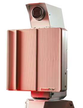
GML Functionality a Game-Changer for Tunnel Excavation
 Orica’s Senior Manager – Measurement Technology, Benny Chen
 GroundProbe’s Product Manager – Lasers & Sensors, Nick Carter
 GroundProbe’s Lead – Tunneling Solutions, Peter Ayres
When it comes to tunnel excavation GroundProbe’s state-of-the-art Geotech Monitoring LiDAR technology (GML) significantly increases excavation efficiency, reduces the costs associated with scaling rework and avoids unnecessary wastage.
GML technology has achieved an efficient and effective excavation cycle where each stage of the constructions is completed to design and at the lowest cost and time.
Typically, tunnelling excavation requires continuous checking throughout the scaling stage of the cycle. It is a time-consuming process that involves data collection, transfer and analysis against the as-built and design by various construction personnel.
Up until now, operators around the globe share a common challenge on excavation sites identifying areas that require extensive rework – without having quality information available on site in near real time. The process has resulted in lost productivity and increased costs associated with rework.
GML technology provides an efficient and effective solution combining high-speed computing and high-resolution LiDAR technology to produce near real-time in-situ construction verification and rectification. And, it provides live guidance while the spraying operation is in progress.
Ultimately, it has significantly reduced the amount of rework associated with typical tunnelling operations. The technology allows shotcrete spray to be applied to design thickness with adequate coverage determined before completion of the support stage.
Computing Technology and LiDAR
Since 2016, there has been rapid development and adoption of high-speed embedded computing platforms in construction operations, largely due to the global development of algorithms and processor cores for machine learning platforms and real-time autonomous vehicle projects.
With the introduction of high-speed and high-resolution laser scanners, the ability for digitisation of as-built scanning at high definition quality is now possible. It has significantly changed the ability to produce Computer Aided Design (CAD) models from scan data and to validate construction against design models.
Current Building Information Model (BIM) construction methods use laser scanners to scan as-built construction elements. They follow the conventional design, construct, verify and remediate methodology with the information transferred to a site office for processing and analysis to determine if construction is in accordance with specifications.
Construction Cycle
In a typical construction cycle the compliance of construction elements in spatial and relative terms is not known until the survey stage is completed. By that time, any identified rework is then required to take place during subsequent construction stages and results in lost productivity and increased costs associated with rework.
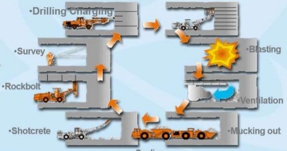
Figure 1: Typical NATM Construction Cycle
It is during the scaling stage of the construction cycle that the GML comes to the fore and demonstrates its state-of-the-art capability.
GML Application
In-Situ Construction Verification and Rectification in BIM
The GML can leverage a near real-time in situ technology to guide the construction crew to detect and rectify possible construction deficiencies whilst the work is being completed. It involves a single operator using a scanner, tablet, and tripod to scan the area, with construction design profiles loaded into the system before scanning occurs.
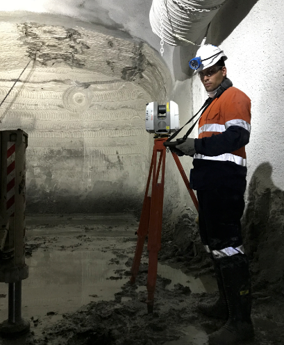
Figure 2: GML Deployment Set-Up
Deployment
The GML’s position next to the front stabilisation jack of the shotcrete rig allows it to remain securely and safely in place during the entire spray sequence allowing for a wide scan area without obstruction to the rig.
The process involves:
- GML completes a baseline scan two minutes before the shotcrete operator starts to spray.
- Shotcrete operator sprays.
- After shotcrete operator is satisfied with the first pass the boom is lowered and a second scan is captured.
- The shotcrete operator receives scan results on a digital device in near real time identifying deficiency areas, as shown in Figure 3.
- Any thin areas are resprayed using a cap lamp or laser pointer guided by the scanner operator.
- A final scan confirms results.
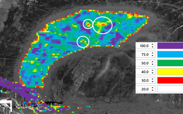
Figure 3: Shotcrete application visualised with adjustable colour thresholds. The results are colour coded and can be adjusted according to the thickness specification for each shotcrete application
Typically, information transfer has been a time-consuming process involving the issue of reports which require analysis and distribution via email to various site personnel and can take several hours to complete.
The GML uses a purpose-designed client-to-server architecture system that enables the scanner operator to attach a tablet to a networked docking station and run synchronisation software to copy the data to a central server.
The data is easily accessed live from the server by site personnel using GroundProbe’s SSR-Viewer software, which makes the full dataset available and accessible to site personnel in near real time.
In addition, the GML has been designed to meet IP54 specifications. Combined with a protective cover during operation, they provide effective protection of equipment in harsh underground conditions without impacting the scanner’s functionality.
In-Situ Excavation Guidance
During excavation, GML provides live guidance to site engineers and machine operators. It helps them to gain a rapid understanding of whether the excavation has been completed to a point where the next sequential activity can be commenced, or if more work is required to reach the minimum profile.
The GML helps to solve the constraints associated with road header tunnelling where the typical accuracy of machine-based positioning systems is considered to be 50mm at a maximum. At this level, a road header guidance system is often used as an engineering control over the excavation process, rather than a verification method to determine design compliance.
Excavation compliance is then typically completed using standard surveying techniques, which only samples certain points on the surface of the excavation for comparison against the design profile. This requires mobilisation of a surveying crew, the set-up, data acquisition and usually, calculation and reporting in an office environment.
In the absence of a road header guidance system, the GML methodology can be used as a ‘stop-go’ system of guiding excavation.
Measurement Accuracy
By comparing the results of existing shotcrete thickness reports produced by standard survey pick-ups against the thickness reported by the GML scanner, the measurement accuracy of shotcrete thickness against the existing total station pick up by survey control is verified.
When the GML is setup next to the total station during pickup, to scan the excavated sections before any ground support and bolts are installed, both can be used to complete the final scan.
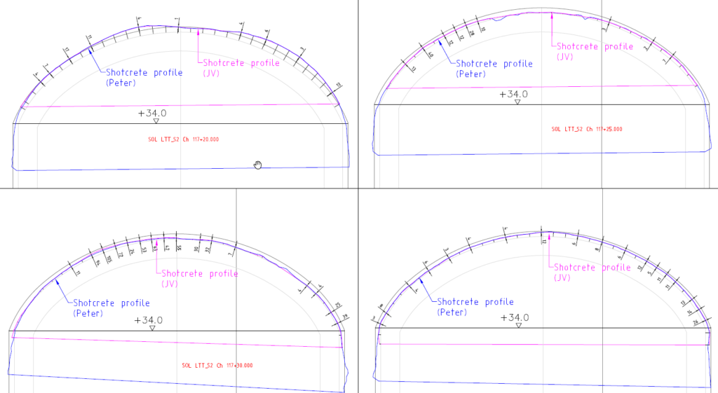
Figure 4: GML & Total Station Comparison Results
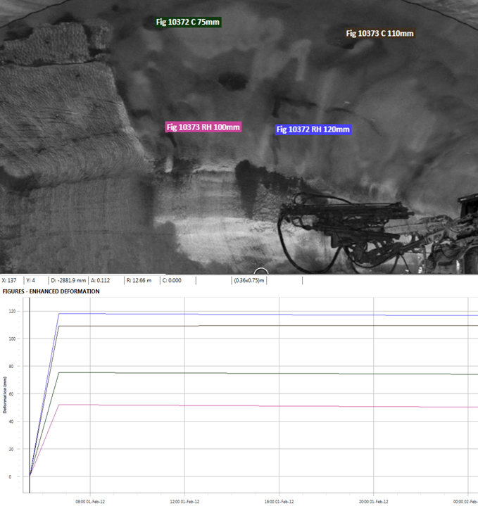
Figure 5: GML & Drill Test Comparison Results. The GML has been used to verify deployment of drilled core samples to check the thickness. It scans the section before ground support is installed after the shotcrete is cured and test holes deployed. This figure shows the drill results in the GML SSR-Viewer software. The photo captures a realistic image produced by the GML data and clearly shows the marked holes. For each marked hole, a group of points are selected, creating annotated figures. An average thickness measurement was computed for each of the annotated group of points.
Case Study: NorthConnex Tunnel Project (Sydney, Australia)
The GroundProbe GML system was used effectively during construction of the NorthConnex Tunnel – a nine-kilometre twin tunnel linking the Greater Sydney region.
The GML technology allowed completion of 35 x 120m sections of road tunnel without rework. Completion of the final lining work for the 4.2km of road tunnels took just 2.5 months. The project used approximately 60m3 of shotcrete per day and within the first month of utilising GML technology the shotcrete order reduced by 30%.
During the final lining application, shotcrete was sprayed continuously from cross passage to cross passage at 120m sections, saving the overall time and costs normally associated with rework.
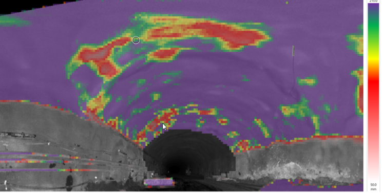
Figure 6: NorthConnex Tunnelling Project. Non-Compliant areas that required rework. Initially, the rig and crew were required to advance 4m to 6m sections during the shotcreting process to guide and spray to the desired thickness. This figure shows the completed sprayed sections which have thin spots and the areas of overspray which require rework.
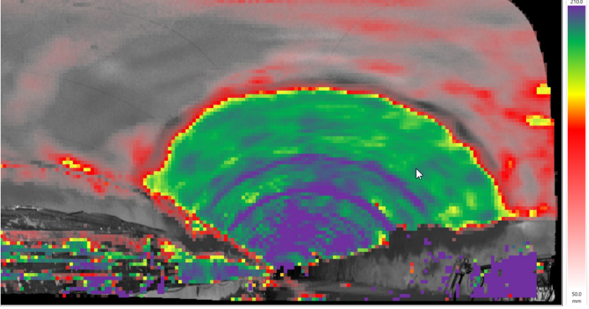
Figure 7: Spray section showing compliance against design with reduced overspray. The GML was setup along the shotcrete rig to scan and guide the shotcrete operator to spray 8m sections at a time, allowing the system to operate in cycle with the spraying process. The speed at which thickness data is produced in-situ has a significant role in time critical applications.
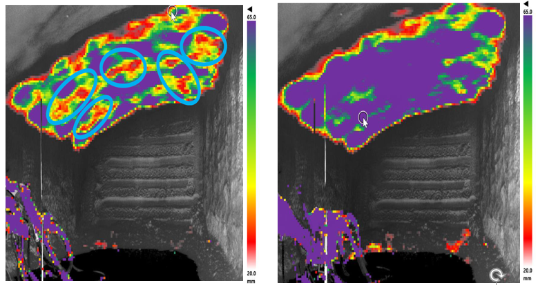
Figure 8: The image on the left shows under spray areas in red (gap between the bolts). The image on the right identifies overspray sections in purple. It shows coverage of bolts by the sprayer which were assumed to cover the bolts sufficiently. The GML showed it was leaving large areas of under spray between the bolts and there were areas of overspray across the entire area.
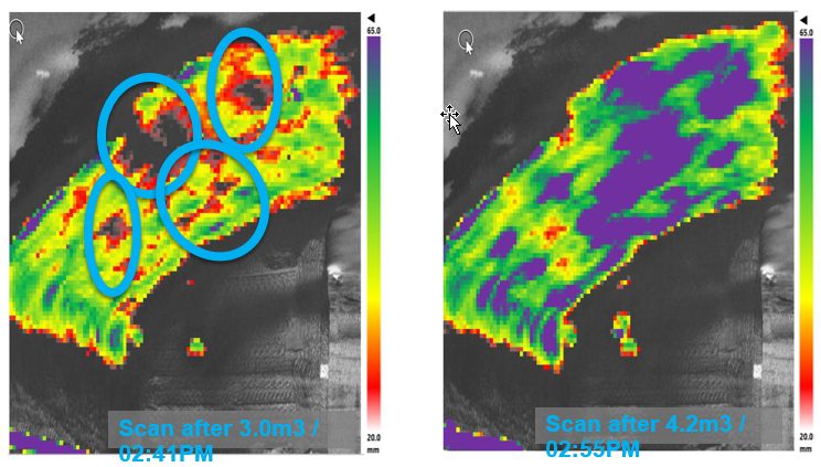
Figure 9: The image shows the shotcrete operator was able to detect thin areas and rectify them on the spot using GML. The guidance achieved efficiencies in the early stages of the project with only a minimal amount of overspray occurring.
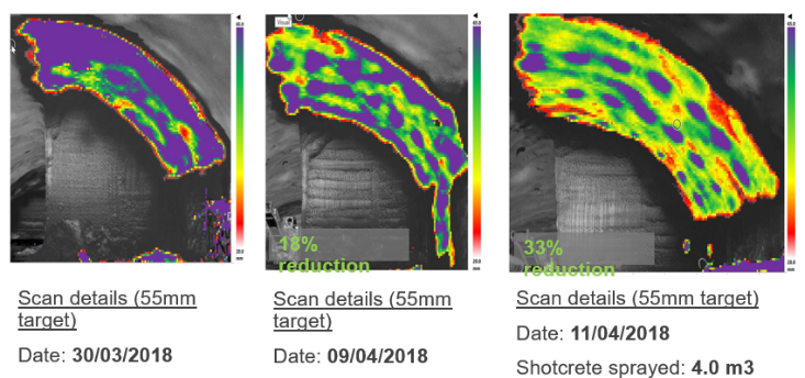
Figure 10: Shows the reduction of overspray areas. Within two weeks there was a 33% reduction of shotcrete used.
The benefits of using GML in projects in terms of quality, cost and time are evident. Rework and verification can now take place at the optimal time during tunnel construction.
It will be exciting to see this technology continue to develop into the future.
Read More
This article is a summary of the paper presented at the ITA-AITES World Tunnel Congress, WTC2020 and 46th General Assembly Kuala Lumpur Convention Centre, Malaysia 15-21 May 2020.


